Buck Converter Inductor Equation
Buck Converter Output Filter Inductor Goes from Critical to Discontinuous Operation. You can read the application guide by ROHM Semicondutors to know more on how the formula is derived but since you have asked for a direct answer you can use the formula.

How To Increase Efficiency And Mitigate Power Loss In Buck Converters Technical Articles
Follow both sections 31 and 32 to find the right inductance.

Buck converter inductor equation. The inductor current increase is equal to the inductor current decrease. Therefore the input current is a highly dynamic waveform. L L c for operating buck converter in DCM.
Inductor Calculation of Buck Converter Example for Coil selection. Core Materials Used in PWM Converters Designers have routinely tended to specify Molypermalloy powder materials for filter inductors used in high-frequency power converters and pulse-width-modulators PWM switched regulators because of the. L 105L c for operating buck converter in CCM.
Determine the operating conditions of the buck converter. The critical inductance value can be easily found by using previously derived I Lmin equation where setting I Lmin 0 in the equation. Inductor and capacitor forms a low-pass filter in a buck converter.
Select the largest value of inductance calculated from either equations 3 and 4. Most of the time the inductor will be selected to reach the required output voltage ripple especially when the DC-DC converter will directly supply the IC without the filtering of the low drop out linear regulators. If the output voltage and the output filter inductor current are chosen to be the state variables of the buck converter then the state vector of the buck converter is.
Integrated circuit used to build the buck converter. Maximum input voltage Vin max Minimum input voltage Vin min Maximum output current. Rectangular pulses of voltage into an inductor result in a triangular current waveform.
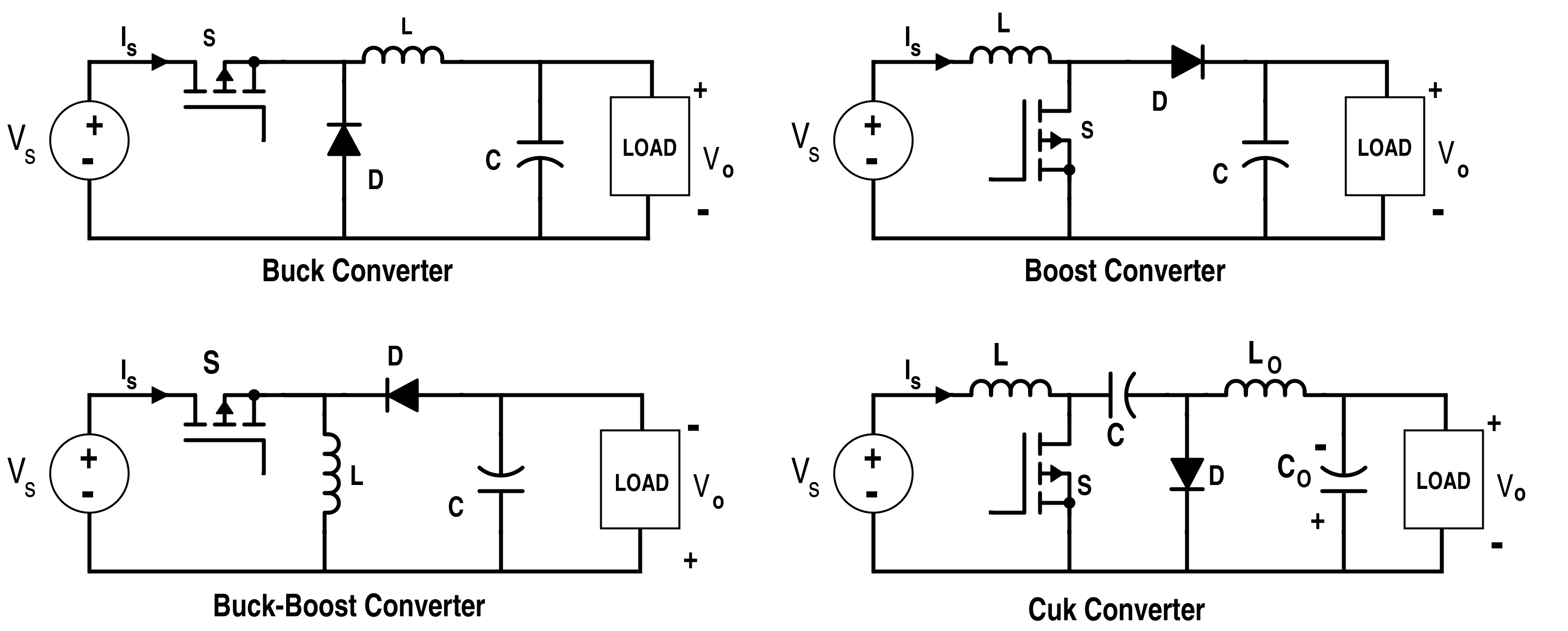
The buck converter has the filter inductor on the output side which provides a smooth continuous output current waveform to the load. L Vi-Vo2 DT. Basic Buck Boost Equations.
The corner frequency the LC filter is always designed to at low frequency to attenuate switching ripple. Basic Calculation of an Inverting Buck-Boost Power Stage However most of the converters are already optimized for specific inductance ranges which are described in the data sheet. VINmin and VINmax 2.
Its value will result from the following equation. For device datasheets where no inductor range is given an inductor that satisfies both buck and boost mode conditions must be chosen. Efficie Application Notency of Buck Converter above-mentioned calculation for the conduction loss of the MOSFET the loss can be calculated in more detail by using the ramp waveform for the inductor current calculation.
Power dissipation equation of the diode. For calculating inductors in buck boost SMPS circuits we could derive the following two concluding formulas for a buck converter and for a boost converter respectively. This could be considered a qualitative benefit but requires special considerations for big load transients.
The converter uses a transistor switch typically a MOSFET to pulse width modulate the voltage into an inductor. - VIN 12V Input Voltage - VOUT 33V Output Voltage - IOUT 2A Output Current - r 03 Output Current Ripple Ratio - VSW 030 ON State Voltage Drop of Switching Element Q1. Vo DVin ---------- For Buck Converter.
When selecting an inductor for a buck converter the following parameters need to be defined. This formula will help you in calculating the value of Inductor in Henry it gives a rough figure but it should work fine for your application. Buck Converter Power Stage 11 Necessary Parameters of the Power Stage The following four parameters are needed to calculate the power stage.
Vo Vin 1 D ---------- For Boost Converter. 7112 x state vector x 1 x 2 v C i L. Buck Switching Converter Design Equations The buck converter is a high efficiency step-down DCDC switching converter.
I Lmin 0 I L-I L 2. Here D Duty Cycle which is Transistor ON time ON. The input is exposed to the switch S1.
Lets first understand the various parameters involved with a buck converter. 2 2 12. For the synchronous buck converter the change in inductor current during the high side MOSFET Q1 on time is equal to the change during the MOSFETs off time.
For operating buck converter in CCM mode the inductor value is chosen more than critical inductance. As a rule of thumb current ripple of inductor is always designed to be around 30 of average inductor current. In this case use the recommended value and calculate the inductor current ripple IL1PP which is a rearrangement of Equation.
Peak inductor current ipk Its the maximum amount of current that an inductor can store before getting saturated.

Buck Converter Design Tutorial Complete Equation Derivation And Design Sample Energy Storage Inductors Design Tutorials

Power Supply Design Notes Let S Build A Bidirectional Buck Boost Converter With Sic Mosfet Power Electronics News

Current And Voltage Stress On The Power Components Of The 5l Buck Download Scientific Diagram

Inductor Behavior And Buck Converter Explained Youtube
Design Buck Converter To Meet Output Ripple Voltage Specs Electrical Engineering Stack Exchange

Positive Buck Regulator Makes Negative Boost Dc Dc Converter Analog Devices
Dc Dc Buck Converter With Arduino Uno Seyed Amir Alavi

Buck Converter Step Down Chopper Electrical4u
Passive Filter Design Concept Of Buck Regulators For Ultra Low Noise Applications Article Mps

Inductor Voltage And Current Of Buck Boost Converter In Pccm Download Scientific Diagram

Power Supply Design Notes Simulating A Buck Converter Power Electronics News

Passive Filter Design Concept Of Buck Regulators For Ultra Low Noise Applications Passive Components Blog

Buck Converter And Its Inductor Current And Output Voltage Download Scientific Diagram

Proposed Tapped Inductor Buck Converter Download Scientific Diagram

Pin On Electronic Circuits

Calculating Size Of Cap Inductor For Buck Convertor Electrical Engineering Stack Exchange
Buck Boost Converter What Is It Formula And Circuit Diagram Electrical4u

Fundamental Circuit Diagrams Of Dc Dc Converters Types A Buck B Download Scientific Diagram
Analysis Of Four Dc Dc Converters In Equilibrium Technical Articles
Posting Komentar untuk "Buck Converter Inductor Equation"