Buck Step Down Converter Calculator
DC-DC converters are also known as Choppers. This application note gives the formulas to calculate the power stage of a synchronous buck operating in.
Basic Calculation Of A Buck Converter S Power Stage Richtek Technology
Non-isolated converters are ideal for all board level circuits where local conversion is required.

Buck step down converter calculator. 3A 12MHz 55V Synchronous Step-Down Converter In WDFN-8L 2x2. The solid state device can be a Power MOSFET or IGBT. The circuit for the DC-DC step-down Buck converter would have the LM7809 voltage regulator two capacitors with capacitance value of 033F and 01F.
This tool is an universal tool to help you with this process. Step-down buck switching regulators Efficient conversion of an input voltage to a lower output voltage With over 1000 unique devices we own the industrys most comprehensive portfolio of high-efficiency DCDC step-down buck switching regulators. Buck converters works 95 or with more higher efficiency for integrated circuits.
Home How Tos Theory Power Electronics DC-DC Voltage Converters 6212 Buck Converter - Component Calculator. I would be. This application note covers the steps required in choosing the inductor and to calculate the value used in buck regulator IC circuits.
Modern step-down switching regulators and controllers are available with internal architectures that are optimized for applications that have specific goals such as power savings high efficiency or low cost. Saturation voltage of the output transistor. These switching voltage regulators offer typical input voltage capability from less than 2 V up to 100 V switching frequencies up to 4 MHz and high efficiency op.
I am using a Step Down Converterto step down 33V to 18V with a Load current of 500mA. 1 VINmax maximum input voltage VOUT output voltage SLVA477BDecember 2011Revised August 2015 Basic Calculation of a Buck Converters. These equations will allow the power-supply designer to optimize components for noise immunity.
Pull down resistor for transistor constant R SC. DC-DC step-down Buck converter circuit. Input and output noise in buck step-down converters can concern the system designer.
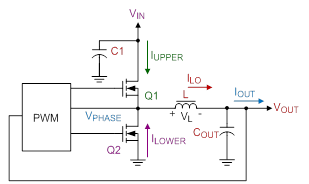
I have an output inductor of 10uH and 12A rated current. The synchronous buck converter is used to step a voltage down from a higher voltage to a lower voltage. The Calculation of Output DC Offset for ACOT Control Buck Converter with Feed-forward Compensator.
Switching Converter Power Supply Calculator. It is a high efficiency step-down DCDC switching converter. 6212 Buck Converter - Component Calculator.
Synchronous buck converters are very popular in industry today and provide high efficiency solutions for a wide range of applications. The LM7809 voltage regulator is placed in the desired position on the circuit board. If you ever worked with the MC34063 Switching Controller you know what a pain it is to calculate all the part values.
You can calculate any standard application such as step-up step-down inverting and step-up-down. Here we will have a look at the Step Down Chopper or Buck converter which reduces the input DC voltage to a specified DC output voltage. I am trying to calculate power dissipation of the converter.
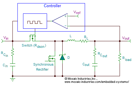
A buck converter is a specific type of switching regulator that steps down. The input voltage source is connected to a controllable solid state device which operates as a switch. By directly means that buck converter is non-isolated DC converter.
This application note provides a theoretical explanation of the individual contributions of conducted noise on the input and output sides of buck converters. The following is a list of products released in the last. Figure 3 below shows the corresponding circuit Figure 3.
A buck converter is a simple converter that is used to step down the voltage and step up the current. I have designed my converter with the help of this TI Buck converter app note. Step-down switching regulators also called buck converters output a regulated voltage level that is less than the input voltage.
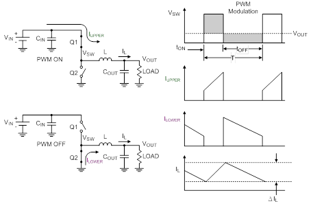
Step-Down Buck Converters Step-Down Buck Controllers. A typical Buck converter is shown below. The maximum input voltage is used because this leads to the maximum switch current.
MC34063 Switching Controller Universal Calculator. A buck converter steps down the applied DC input voltage level directly. Multi-Phase Step-Down Controllers.
Analog Devices manufactures a broad line of high performance step-down buck switching regulator ICs and buck switching controller ICs with both synchronous and nonsynchronous switches. Duty-cycle is one key to measure the buck converters output current capability. The following is a design tool which calculates the parameters for a buck converter boost converter or Buck-Boost Converter - Step-downStep-up or invertingThe calculator assumes that during the normal load the inductor is in continuous mode meaning that the inductor never fully discharges its current.
Buck Step-Down Converter Switching regulators are used in a variety of applications to provide stable and efficient power conversion. The first step to calculate the switch current is to determine the duty cycle D for the maximum input voltage.
Buck Converter Design For Pmdc Motor Physics Forums
Buck Converter Step Down Regulator


Calculating Size Of Cap Inductor For Buck Convertor Electrical Engineering Stack Exchange

How To Apply Dc To Dc Step Down Buck Regulators Successfully Analog Devices
Basic Calculation Of A Buck Converter S Power Stage Richtek Technology
Buck Converter Design Tutorial Complete Equation Derivation And Design Sample


The Calculator Diy Dc Dc Boost Calculator Adafruit Learning System

Mp1584 3a 1 5mhz 28v Step Down Converter Mps

Using Ceramic Output Capacitors With The Max1734 Voltage Mode Buck Converter
Basic Operation Of Step Down Converters Basic Knowledge Rohm Tech Web Technical Information Site Of Power Supply Design
Example Of Derivation For A Step Down Converter Basic Knowledge Rohm Tech Web Technical Information Site Of Power Supply Design
Switching Losses In Synchronous Rectifying Step Down Converters Basic Knowledge Rohm Tech Web Technical Information Site Of Power Supply Design

Mathcad Calculates Input Capacitor For Step Down Buck Regulator

Controller Ic Power Consumption Losses In A Synchronous Rectifying Step Down Converter Basic Knowledge Rohm Tech Web Technical Information Site Of Power Supply Design

Buck Boost Converter What Is It Formula And Circuit Diagram Electrical4u
Designing Step Down Buck Switching Regulators How To Choose Inductor And Capacitor Values
Making A Voltage Inverter From A Buck Step Down Dc Dc Converter
Inductor Calculation For Buck Converter Ic

Buck Converter Design Tutorial Complete Equation Derivation And Design Sample
Posting Komentar untuk "Buck Step Down Converter Calculator"