Voltage Frequency Converter Calculator
The formula shows that the capacitors reactance X C is large at low frequencies and small at high frequencies. About Press Copyright Contact us Creators Advertise Developers Terms Privacy Policy Safety How YouTube works Test new features Press Copyright Contact us Creators.

Rms Value Average Value Peak Value Peak Factor Form Factor In Ac Root Mean Square Electronic Engineering Rms
Voltage-to-Frequency and Frequency-to-Voltage Converter FEATURES High Linearity 001 Max at 10 kHz FS 005 Max at 100 kHz FS 02 Max at 500 kHz FS Output TTLCMOS-Compatible VF or FV Conversion 6 Decade Dynamic Range Voltage or Current Input Reliable Monolithic Construction MIL-STD-883-Compliant Versions Available PIN CONFIGURATION TOP.

Voltage frequency converter calculator. 3 ILIMmin minimum value of the current limit of the integrated switch given in the data sheet. The first design is using the IC VFC32 which is an advanced voltage to frequency converter device from BURR-BROWN specifically designed to produce an extremely proportional frequency response to the fed input voltage for a given voltage to frequency. The digital output is an open collector and the digital pulse train repetition rate is propor-tional to the amplitude of the analog input voltage.
This Frequency to Voltage Converter Circuit can be built on a PCB for greater precision. The cutoff frequency of a device microphone amplifier loudspeaker is the frequency at which the output voltage level is decreased to a value of 3 dB below the input voltage level 0 dB. Hz to voltage converter is used in calculations.
The calculated impedance is a measure of the capacitors resistance to the signal at a specific frequency which passes through it. The voltage V in volts V is equal to the square root of the power P in watts W times the resistance R in ohms . We can use two TC9400 ICs and operate both of them in the mode of frequency to voltage conversion in order to obtain the frequency difference measurements.
It is the reciprocal of the product of R resistance and C capacitance for values Z1R and Z21sC in the general integrator diagram. F OUT V OUT IA 100 kHz10 V 50 kHz. The VFCs output FOUT varies linearly with V OUT IA.
How the Frequency to Voltage Converter Circuit Works. The VFC320 monolithic voltage-to-frequency and frequency-to-voltage converter provides a simple low cost method of convert-ing analog signals into digital pulses. The basic operation of the proposed frequency to voltage converter circuit is based of a charge-and-balance theory.
Integrator frequency calculator uses integrator_frequency_radians 1 Resistance Capacitance to calculate the Integrator Frequency The Integrator frequency is the inverse of integrator time constant. Where 100 kHz is the maximum frequency output 10 V is the maximum input voltage. This frequency to wavelength calculator helps you determine the wavelength of a waveform based on the frequency.
The capacitive reactance varies inversely with the changing frequency of the applied AC voltage. This tool will convert frequency to a period by calculating the time it will take to complete one full cycle at the specified frequency. It assumes that the wave is traveling at the speed of light which is the case for most wireless signals.
The RC oscillator has to be located in close proximity over the KA331 IC. VOUT desired output voltage D duty cycle calculated in Equation 1 fS minimum switching frequency of the converter L selected inductor value It now has to be determined if the selected IC can deliver the maximum output current. The entry unit of frequency can be modified the output wavelength is calculated in meters.
A voltage to frequency converter circuit converts a proportionately varying input voltage int a proportionately varying output frequency. The power P in watts W is equal to the voltage V in volts V times the current I in amps A. TC9400 is a frequency to voltage and voltage to frequency converter IC.
The power P in watts W is equal to the squared voltage V in volts V divided by the resistance R in ohms . 3 dB corresponds to a factor of 12 07071 which is 7071 of the input voltage. The formula used to calculate the period of one cycle is.
F-to-V Calculations from AN-279 In this mode the primary design parameters are F IN-MAX signal bandwidth F AVG mechanical bandwidth and V OUT-MAX output voltage for F IN-MAXFrom these default component values are calculated for C INT R INT and C OS which may be afterwards manually adjustedAfter the circuit parameters have been entered V OUT and F IN can be. For each frequency entered a conversion scale will display for a range of frequency versus period values. The input signal frequency is calculated to be conforming the expression Vin R1 and this value is processed by the relevant IC opamp through integration with the aid of C2.
The key part of the circuit is the oscillator to RC. Its basic circuit connections include three resistors two capacitors and reference voltage.

Rms Voltage Calculator From Average Value Peak Peak To Peak Value Electronic Engineering Peak To Peak Rms
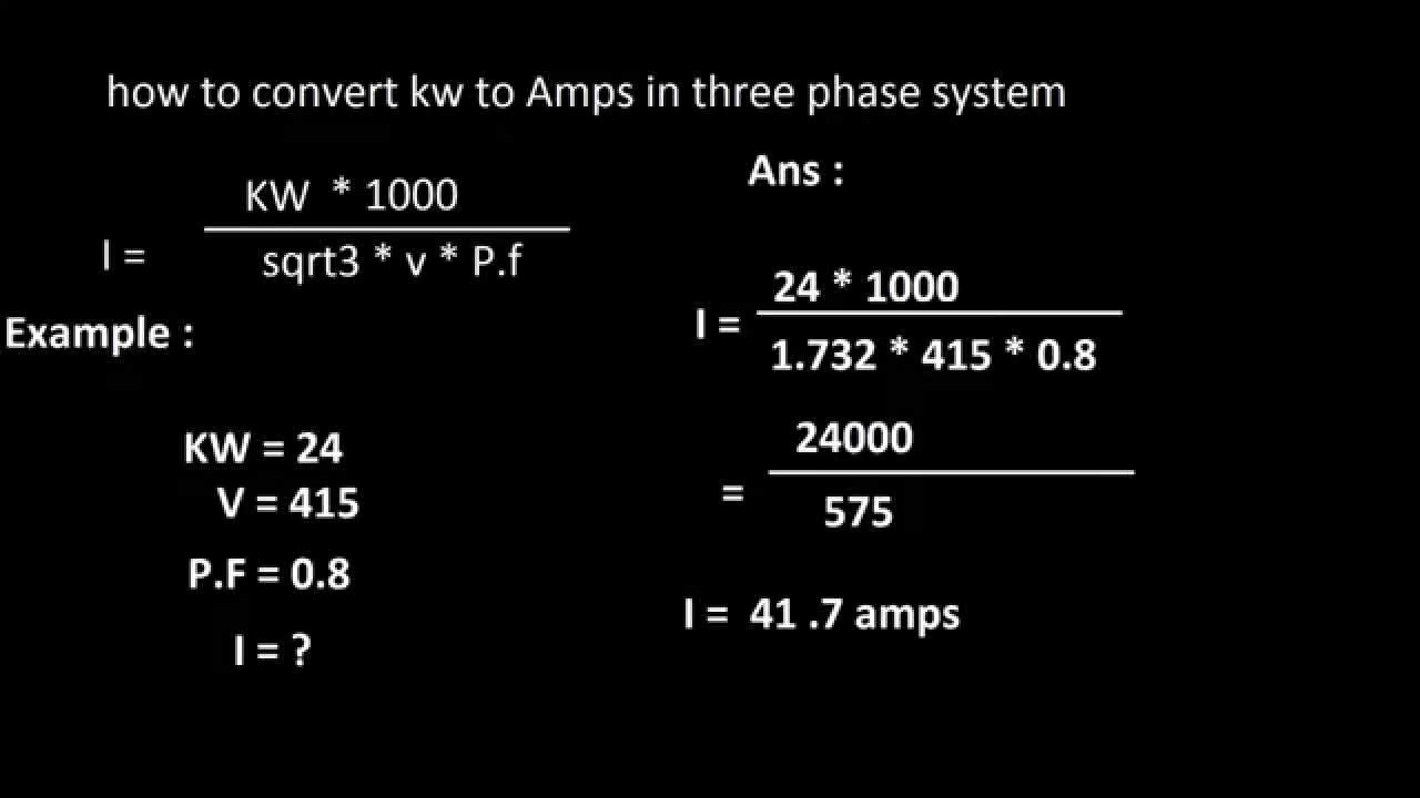
How To Convert Kw To Amps In 3 Phase System System Amp Converter

0 01hz To 500khz Adjustable Tone Frequency Decoder Circuit Using Lm567 Circuit Frequencies Detection

Free Shipping Dc Dc Voltage Converter Module 12v Turn 3 3 5 12v Power Module Blue Voltage Converter Converter Development Boards

Rms Voltage Calculator Electronics Basics Electronic Engineering Electrical Engineering

Amps To Kilowatts Kw Electrical Conversion Calculator Math Genius Math Lessons Math Methods

Pin On Electronic Circuit

Electronics Plus App Eatures 100 Electronics Electrical And Drone Rc Plane Quadcopter Calculator 3500 Component Datasheet Collect App Arduino Capacitor

Amp Hours Ah To Kilowatt Hours Kwh Conversion Calculator Teaching Mathematics Math Methods High School Math Classroom

Power Calculator For Generators Convert Kva To Kw Kw To Kva Kw To Hp Converter Power Generation

Capacitor Value Converter Uf Pf Nf This Feature Of Caps Converter Will Convert Your Value Into Microfarads f Picofarads Capacitor Ohms Law Time Constant

Pin On Projects To Try

Ferrite Transformer Turns Calculation With Example Toroidal Transformer Switched Mode Power Supply Electrical Transformers

Configuration For Lm2907 In 2021 Circuit Voltage Converter Circuit Diagram
Rms Value Average Value Peak Value Peak Factor Form Factor In Ac Root Mean Square Electronic Engineering Rms

Db Calculate Decibel Calculation Db Calculator Voltage Power Ratio Sound Pressure Level Matching Dba Spl Sound Pressur Cause And Effect Information Age Sound

Watts To Amps Calculator Conversion Dc Ac 1 3 Phase Simple Calculator Induction Heating Power Electronics

Kva To Amps Calculator How To Convert Kva To Amps In 2021 Basic Electrical Engineering Electrical Circuit Diagram Electrical Engineering Technology

Induction Motor Synchronous Speed N Sub S Sub Calculator Electronic Engineering Power Engineering Formula
Posting Komentar untuk "Voltage Frequency Converter Calculator"